![]()
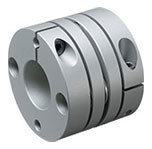
CPE Models Specifications
CPE Models
[Specifications]
| Model | Torque | Misalignment | Max. rotation speed [min-1] | Torsional stiffness [N・m/rad] | Moment of inertia [kg・m2] | Mass [kg] | ||
|---|---|---|---|---|---|---|---|---|
| Nominal [N・m] | Max. [N・m] | Parallel [mm] | Angular [°] | |||||
| CPE-19 | 0.7 | 1.4 | 0.2 | 1 | 6000 | 500 | 0.69×10⁻⁶ | 0.015 |
| CPE-29 | 2 | 4 | 0.2 | 1 | 6000 | 700 | 5.80×10⁻⁶ | 0.050 |
| CPE-39 | 5 | 10 | 0.2 | 1 | 6000 | 1900 | 18.50×10⁻⁶ | 0.080 |
*Torques for CPE-19 are values when the bore diameter is at least equal to 4 mm.
*Max. rotation speed does not take into account dynamic balance.
*The moment of inertia and mass are measured for the maximum bore diameter.
[Dimensions]

| Model | d1, d2 | D | L | L1 | L2 | M | A | |
|---|---|---|---|---|---|---|---|---|
| Min. | Max. | |||||||
| CPE-19 | 3 | 8 | 19 | 19.4 | 6 | 2.75 | M2.5 | 6 |
| CPE-29 | 6 | 14 | 29 | 30 | 9.5 | 4.5 | M3 | 10 |
| CPE-39 | 8 | 20 | 39 | 40 | 12.5 | 6 | M4 | 14 |
*Insert the shaft to at least the dimension L1. (Note that the shaft cannot go all the way through.)
*The recommended processing tolerance for paired mounting shafts is the h7 class.
[Standard bore diameter]
| Model | Standard bore diameters d1, d2 [mm] | ||||||||||||||||
|---|---|---|---|---|---|---|---|---|---|---|---|---|---|---|---|---|---|
| 3 | 4 | 5 | 6 | 6.35 | 7 | 8 | 9.525 | 10 | 11 | 12 | 14 | 15 | 16 | 18 | 19 | 20 | |
| CPE-19 | ○ | ● | ● | ● | ● | ● | ● | ||||||||||
| CPE-29 | ● | ● | ● | ● | ● | ● | ● | ● | ● | ||||||||
| CPE-39 | ● | ● | ● | ● | ● | ● | ● | ● | ● | ● | ● | ||||||
*Torque on the CPE-19 with a bore diameter of 3 mm is limited by holding force in the shaft coupling component, so nominal torque is 0.4 N·m and maximum torque is 0.8 N·m.
*Bore diameters between the minimum and maximums shown in the dimensions table are compatible, but bore diameters other than those shown in the above table require a separate bore drilling charge.

Related Product

- Max. rated torque 220 N・m
- Bore ranges 4 mm to 35 mm
- Operating temperature -30℃ to 100℃
 日本語
日本語 English
 Deutsch
 中文
中文 한국어
한국어


