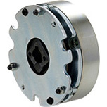
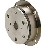
Features of BEW Models
These are basic models of power supplies for controlling electromagnetic clutches and brakes with rated voltages of 45 V DC/90 V DC/180 V DC. The direct current required to operate electromagnetic clutches and brakes can be obtained simply by connecting/inputting using 100 V AC, 200 V AC, or 400 V AC specifications.Power supplies are available with a variety of specifications, including half-wave rectified and full-wave rectified, and are compact and lightweight as well. These are of the terminal block type, which allows easy connection to wiring, with a DC switching terminal.
BEW Models Specifications
BEW Models
[Specifications]
| Model | BEW-2G | BEW-4G | BEW-1R | BEW-2R | BEW-4R |
|---|
| Input voltage | AC100V | ± 10% 50 Hz/60 Hz | ● | | ● | | | ● | ● | | | | |
|---|
| AC200V | | ● | | ● | | | | ● | ● | | |
| AC400V | | | | | ● | | | | | ● | ● |
| Input voltage range | AC 280 V max. | AC 480 V max. | AC90 ~ 140V | AC180 ~ 280V | AC360 ~ 480V |
| Rectification method | Half-wave rectification | For both half- and full-wave rectification |
|---|
| Half-wave | Full-wave | Half-wave | Full-wave | Half-wave | Full-wave |
| Output voltage | DC45V | DC90V | DC45V | DC90V | DC180V | DC45V | DC90V | DC90V | DC180V | DC180V | DC360V |
|---|
| Output current | When the ambient temperature is 20℃ values in () are for an ambient temperature of 60℃ | DC1.0A (DC0.7A) | DC1.0A(DC0.7A) | DC2.0A (DC1.5A) | DC1.0A(DC0.7A) | DC0.7A (DC0.5A) |
|---|
| Output Wattage | When the ambient temperature is 20℃ values in () are for an ambient temperature of 60℃ | 45 W
(25 W) | 90 W
(50 W) | 45 W
(25 W) | 90 W
(50 W) | 180 W
(100 W) | 90 W
(50 W) | 180 W
(100 W) | 90 W
(50 W) | 180 W
(100 W) | 126 W
(90 W) | 252 W
(180 W) |
|---|
| Size settings | Voltage specifications Numbers in parentheses are input voltages | DC45V
(AC100V) | DC90V
(AC200V) | DC45V
(AC100V) | DC90V
(AC200V) | DC180V
(AC400V) | DC45V
(AC100V) | DC90V
(AC100V) | DC90V
(AC200V) | DC180V
(AC200V) | DC180V
(AC400V) | DC360V
(AC400V) |
|---|
●: Applicable
△: Applicable depending on clutch/brake model | 01 | ● | ● | ● | ● | ● | ● | ● | ● | ● | ● | |
| 02 | ● | ● | ● | ● | ● | ● | ● | ● | ● | ● | |
| 03 | ● | ● | ● | ● | ● | ● | ● | ● | ● | ● | |
| 04 | ● | ● | ● | ● | ● | ● | ● | ● | ● | ● | |
| 05 | ● | ● | ● | ● | ● | ● | ● | ● | ● | ● | |
| 06 | ● | ● | ● | ● | ● | ● | ● | ● | ● | ● | |
| 08 | ● | ● | ● | ● | ● | ● | ● | ● | ● | ● | |
| 10 | ● | ● | ● | ● | ● | ● | ● | ● | ● | ● | |
| 12 | | ● | | ● | ● | | ● | ● | ● | ● | |
| 14 | | ● | | ● | ● | | ● | ● | ● | ● | |
| 16 | | ● | | ● | ● | | ● | ● | ● | ● | |
| 18 | | △ | | △ | ● | | ● | △ | ● | ● | |
| 20 | | △ | | △ | ● | | ● | △ | ● | ● | |
| 25 | | △ | | △ | ● | | ● | △ | ● | ● | |
| Applicable clutches/brakes | Miki Pulley Clutches & Brakes, Rated voltage: DC 45/90/180 V | Spring-actuated brake | All |
|---|
| Insulating resistance | Between terminal and body | DC 500 V, 100 M Ω with Megger |
|---|
| Dielectric strength voltage | Between terminal and body | 1500 V AC, 50 Hz, 1 min. | 2000 V AC, 50 Hz, 1 min. | 1500 V AC, 50 Hz, 1 min. | 2000 V AC, 50 Hz, 1 min. |
|---|
| Usage environment | With no condensation | -20℃ to +60℃ |
|---|
| Mass | Per product | 0.04 kg |
|---|
[Dimensions]

[Structure]

[Terminals and Functions]
| Model | Terminal symbol | Terminal name | Function description |
|---|
| BEW(G) | 1-2 | Power supply input terminal | Connector for a commercial power supply |
|---|
| 2-3 | Control terminal | Output is controlled by opening and closing between terminals with a relay or other contact |
| 3-4 | Output terminal | Connector for an electromagnetic clutch or brake |
| BEW(R) | 1-2 | Power supply input terminal | Connector for a commercial power supply |
|---|
| 2-4 | Output terminal (half-wave) | Connector for an electromagnetic clutch or brake (when half-wave rectified) |
| 3-4 | Output terminal (full-wave) | Connector for an electromagnetic clutch or brake (when full-wave rectified)) |
[Characteristics]
Output type
Two systems are available, half-wave rectified and full-wave rectified. Half-wave rectified takes a commercial power supply as the input and generates a halfwave rectified DC voltage on the output side. These power supply devices are known for their very simple construction and low cost, but their voltage pulse is large. They are therefore prone to generating variations in operating response in electromagnetic clutches and brakes, they produce a howling noise when conducting, and they tend to generate more heat from their electromagnetic coils than full-wave rectified supplies or smoothing supplies.
When the above are to be avoided, consider changing to a full-wave rectified supply, smoothing supply, or a DC 24 V specification.
Full-wave rectified power supply devices are known for having smaller voltage pulses than half-wave rectified supplies and tending to have little variation in electromagnetic clutch and brake operating response. They can thus be used not just for spring-actuated brakes but also for electromagnetic-actuated clutches and brakes.
Note that when the rated voltage of the electromagnetic coil does not match the voltage output from the power supply device, you will not be able to obtain the electromagnetic clutch/brake characteristics given in the specifications.
[Wiring Methods and Timing Charts]
BEW(G) Secondary Control (Basic Wiring)

BEW(G) Primary Control (Wire Saving)

BEW(G) Secondary Control (Wire Saving)

BEW(R) Primary Control

![]()


 日本語
日本語 English
 Deutsch
 中文
中文 한국어
한국어


