 日本語
日本語 English
 Deutsch
 中文
中文 한국어
한국어


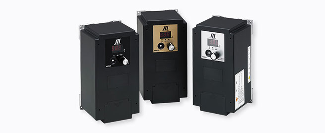
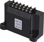
BEH Models (For ultra-high-speed control)

![]()
BEH Models
[Specifications]
| Model | BEH-10G | BEH-20G | BEH-20G-1 | |
|---|---|---|---|---|
| Input voltage | AC200/220V ± 10% | AC200/220V ± 10% | AC100/115V ± 10% | |
| ± 10% Single phase, 50/60 Hz | ||||
| Output voltage | Overexcitation voltage | Initial value 100 V, 0 to 250 V variable | ||
| Constant excitation voltage | Initial value 24 V, 0 to 250 V variable | |||
| Reverse excitation voltage | Initial value 100 V, 0 to 250 V variable | |||
| Voltage control method | PWM control | |||
| Output current | 2 A | 4 A | 4 A | |
| Applicable clutche/brake size | 06 ~ 16 | 06 ~ 31 | 06 ~ 31 | |
| MIKI PULLEY electromagnetic-actuated clutches and brakes Rated voltage DC 24 V | ||||
| Protective functions | Undervoltage protection, overvoltage protection, overcurrent protection/detection, break detection, element overheating protection, input-side fuse (20 A) | |||
| Usage environment | -10 - +50℃ / 10 - 90%RH | |||
| Mass | 0.85kg | 0.9kg | 0.9kg | |
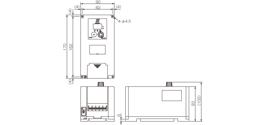
[Dimensions]
[Structure]

[Operating Settings]
| Operating settings SW (SW3) Switch No. | ON (Up) | OFF (Down) | OFF | |
|---|---|---|---|---|
| 1 | Settings/operating modes | Setup mode | Operation mode | OFF |
| 2 | Stand-alone/interlocked mode | Stand-alone mode | Interlocked mode | OFF |
| 3 | Break/overcurrent detection | Enabled | Disabled | OFF |
| 4 | Current/voltage control | Current control | Voltage control | OFF |
| 5 | Control AUX | Enabled | Disabled | OFF |
| 6 | Jog operation | Enabled | Disabled | OFF |
| 7 | Slope operation | Enabled | Disabled | OFF |
| 8 | One-shot operation | Enabled | Disabled | OFF |
[Terminals and Functions]
| Terminal symbol | Terminal name | Function description |
|---|---|---|
| R-S | Power supply input terminal | Connector for a commercial power supply |
| CL-P | Clutch output terminal | Connector for a clutch |
| BR-P | Brake output terminal | Connector for a brake |
| Ground | External ground terminal (third class ground or more) | |
| 1 | Power supply terminal + | Positive terminal of control power supply (shared with the internal supply's +24 V) |
| 2 | Power supply terminal - | Negative terminal of control power supply (shared with the internal supply's 0 V) |
| 3 | Control AUX | When operating switch 5 (AUX operation) is on, executes the operation of the conditions set in the table. |
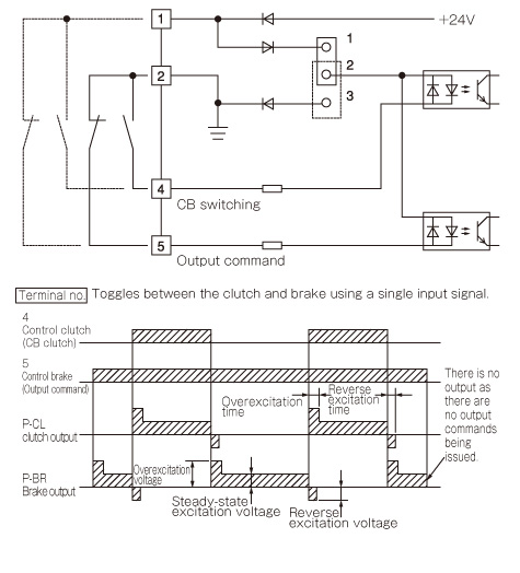
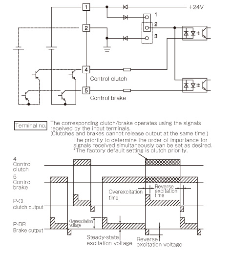
| 4 | Control clutch | Turns output between P and CL on and off. |
| 5 | Control brake | Turns output between P and BR on and off. |
| 6・7 | Alarm output 1 | A relay that operates during an alarm stop (relay output) |
| 8 | Alarm output 2 | Output operates during an alarm stop (transistor output) |
[Characteristics]
Operating response
Noise During Operation
Output Control System
Supply Voltage Fluctuations and Output Voltage
[Wiring methods and timing charts]
Operating mode (Operating Settings SW-2 Off)
Stand-alone operation mode (Operating Settings SW-2 On)

![]()
![]()
![]()
![]()
![]()
![]()