 日本語
日本語 English
 Deutsch
 中文
中文 한국어
한국어


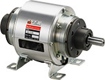
BEW(FH) Models
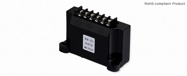

![]()
BEW (FH) Types
[Specifications]
| Model | BEW-1FH | BEW-2FH | BEW-4FH | |||||
|---|---|---|---|---|---|---|---|---|
| Input voltage | 100 V AC | ± 10% 50/60 Hz | ● | ● | ||||
| 200 V AC | ● | ● | ||||||
| 400 V AC | ● | ● | ||||||
| Input voltage range | AC80 ~ 130V | AC170 ~ 300V | AC80 ~ 480V | |||||
| Control method | Overexcitation (full-wave rectified) for 0.5 sec followed by constant excitation (half-wave rectified) | |||||||
| Overexcitation | Constant excitation | Overexcitation | Constant excitation | Overexcitation | Constant excitation | |||
| Output voltage | DC90V | DC45V | DC180V | DC90V | DC360V | DC180V | ||
| Output current | When the ambient temperature is 20℃ values in () are for an ambient temperature of 60℃ | DC1.6A (DC1.3A) Constant excitation | 1.2 A DC (1.0 A DC) Constant excitation | |||||
| Output capacity | When the ambient temperature is 20℃ values in () are for an ambient temperature of 60℃ | 72 W (58 W) Constant excitation | 144 W (117 W) Constant excitation | 216 W (180 W) Constant excitation | ||||
| Size settings | Purpose for use | Using overexcitation | Using weak excitation | Using overexcitation | Using weak excitation | Using overexcitation | Using weak excitation | |
| Clutch/brake rated voltage | DC45V | DC90V | DC90V | DC180V | DC180V | DC360V | ||
| ●: Applicable | 01 | ● | ● | ● | ● | ● | ||
| 02 | ● | ● | ● | ● | ● | |||
| 03 | ● | ● | ● | ● | ● | |||
| 04 | ● | ● | ● | ● | ● | |||
| 05 | ● | ● | ● | ● | ● | |||
| 06 | ● | ● | ● | ● | ● | |||
| 08 | ● | ● | ● | ● | ● | |||
| 10 | ● | ● | ● | ● | ● | |||
| 12 | ● | ● | ● | ● | ||||
| 14 | ● | ● | ● | ● | ||||
| 16 | ● | ● | ● | ● | ||||
| 18 | ● | ● | ● | ● | ||||
| 20 | ● | ● | ● | ● | ||||
| 25 | ● | ● | ● | ● | ||||
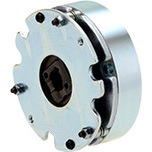
| Applied cutches/brakes | MIKI PULLEY electromagnetic-actuated clutches and brakes Rated voltage DC 45/90/180 V | Spring-actuated brake | ||||||
| Insulating resistance | Between terminal and body | DC 500 V, 100 M Ω with Megger | ||||||
| 2000 V AC, 50 Hz, 1 min. | ||||||||
| Usage environment | With no condensation | -20℃ ~ +60℃ | ||||||
| Mass | Per product | 0.065 kg | ||||||
[Dimensions]

[Structure]

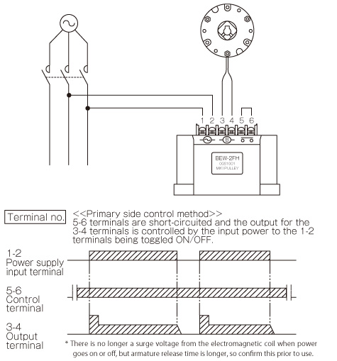
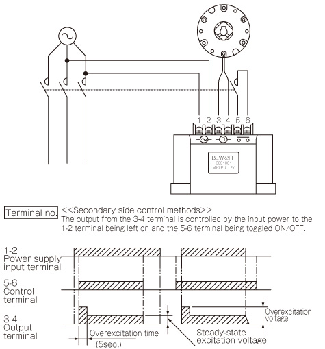
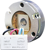
[Terminals and Functions]
| Terminal symbol | Terminal name | Function description |
|---|---|---|
| 1-2 | Power supply input terminal | Connector for a commercial power supply |
| 3-4 | Output terminal | Connector for an electromagnetic clutch or brake |
| 5-6 | Control terminal | Output is controlled by opening and closing between terminals with a relay or other contact |
[Characteristics]
Used as Overexcitation Supplies
Use as a weak excitation power supply
[Wiring Methods and Timing Charts]
Primary Control
Secondary Control

![]()
![]()
![]()
![]()
![]()
![]()